

Faster, Clearer Optical Thin Film Design, Analysis, and Optimization
The long-awaited new version of TFCalc is here!
Rebuilt from the ground up for modern Windows environments, TFCalc 5 supports 64-bit architecture and high-resolution displays.
Maintaining the intuitive design workflow users trust, it introduces a bilingual English/Japanese interface, faster parallel calculation, and 3D plotting, build for long-term reliability.
TFCalc 5 Launch Campaign: Get a great deal on TFCalc through the special campaign running until March 31, 2027!
● TFCalc 5 is a one-time purchase product, allowing for long-term use. The initial purchase includes one year of maintenance coverage.
● During the active maintenance period, you are entitled to free version upgrades.
(You may continue to use TFCalc even if you choose not to renew your maintenance.)
● Volume discounts are available for multiple-license purchases. Users of versions 3.5 or 3.6 are eligible for special upgrade pricing.
● A special promotional campaign for new licenses is currently underway! (Valid until March 31, 2027)
Start a free trial or request a quote here.
TFCalc calculates the optical properties of dielectric and metallic thin film coatings, including reflectance, transmittance, absorptance, phase shift, electric field intensity, and color. Capable of handling up to 5,000 layers, TFCalc optimizes coating designs tailored for specialized optical applications. It includes a comprehensive optical constants database and is widely recognized and cited in research papers and conference presentations across academic and corporate R&D teams.
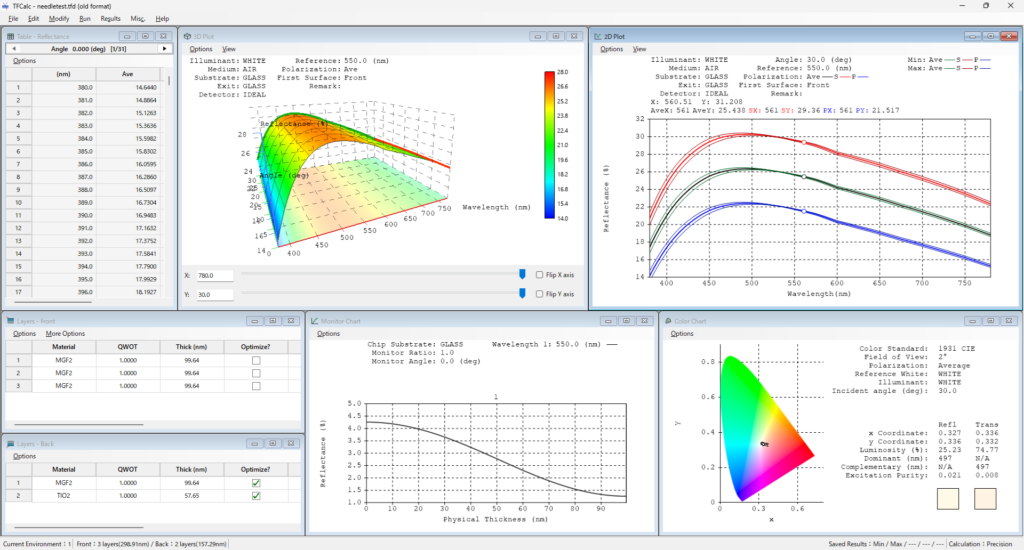
What’s New in TFCalc V5
Multifaceted Analysis
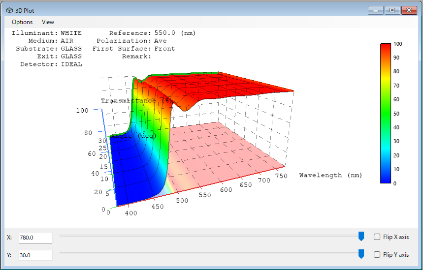
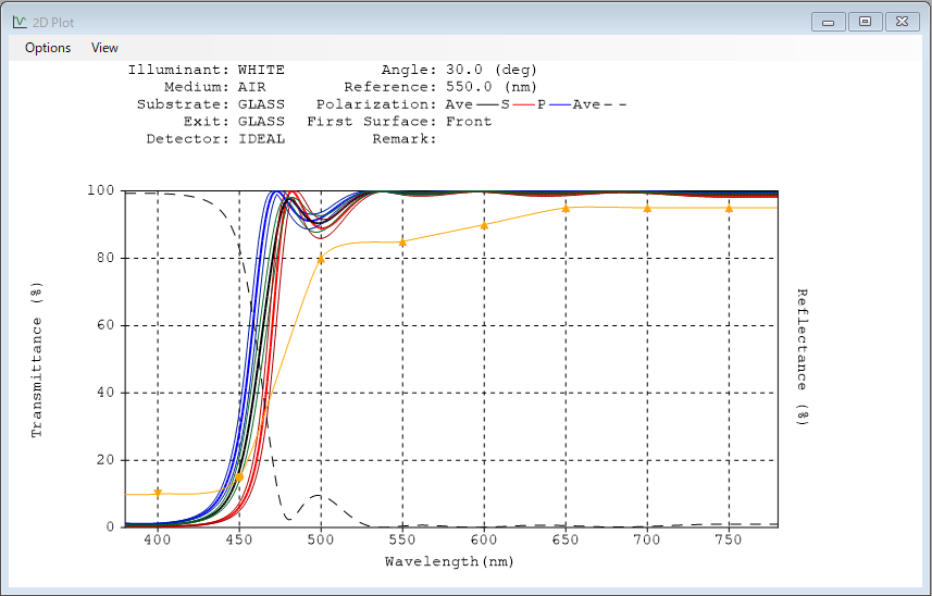
Visualizes spectral characteristics as a 3D plot across wavelength × incident angle × characteristic value, supporting rotation, zooming, and cross-sectional views. 2D plot displays are enhanced with color-coded outputs and auxiliary reference lines.
Accelerated Calculation
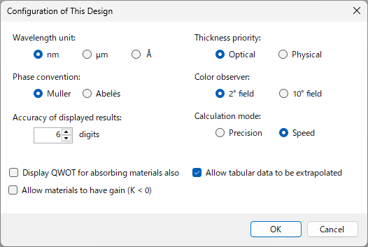
Parallel processing for wavelength-dependent calculations and needle optimization, featuring two computational modes: Precision (accuracy priority, 28-digit decimal operations) and Speed (double precision). Supports multi-core processor calculations.
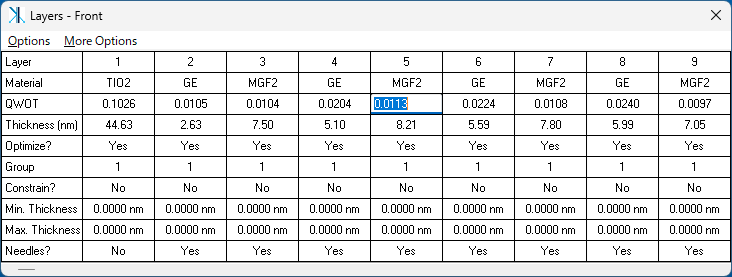
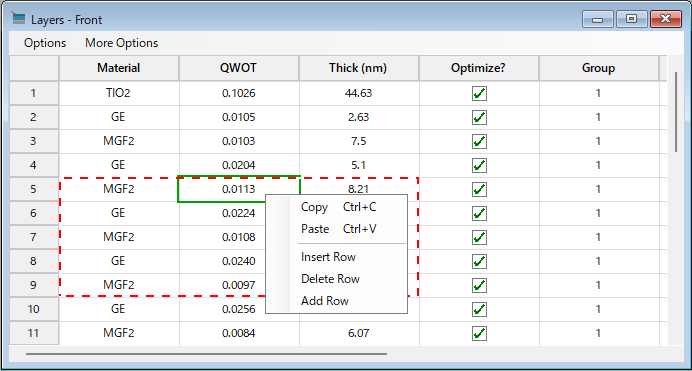
Excel-Like Table UI
Adopts an Excel-style spreadsheet interface for tabular data editing, supporting direct cell operations, copy/paste compatibility with Microsoft Excel, Undo/Redo, and row/column transposition views.
➡
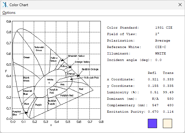
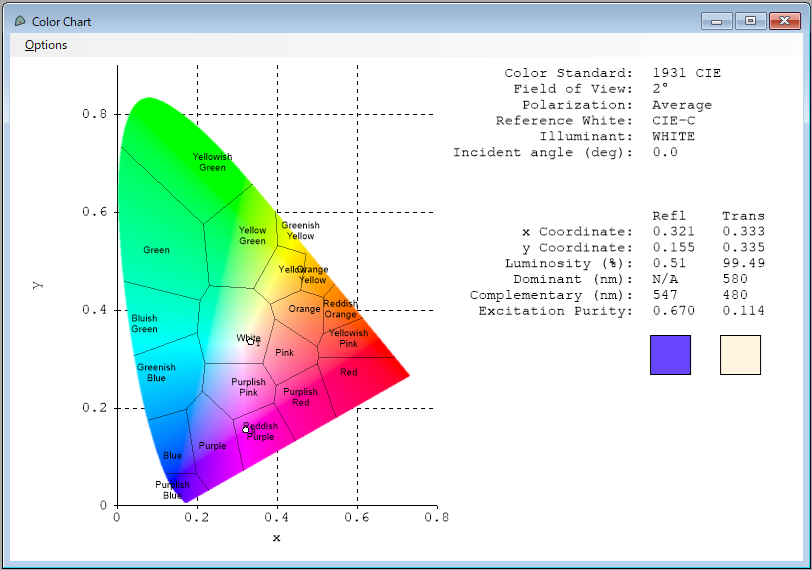
Refreshed Color Chart Window
Modernized color chart display interface.
➡
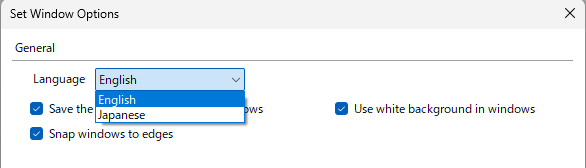
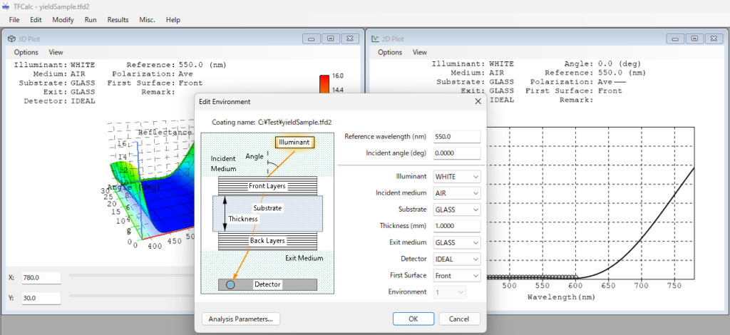
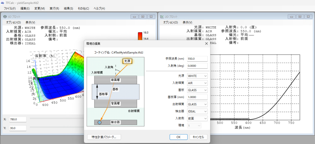
Bilingual UI (English / Japanese)
Easily toggle menus, dialogs, and messages between English and Japanese.
New File Format (.tfd2)
Consolidated storage format that bundles design parameters, saved calculation results, and 3D display states into a single file. Fully supports importing and exporting legacy V3 files for seamless data exchange between V3 and V5.
Comprehensive Feature List
Thin Films
- Set up to 5,000 layers in total on the front and back surfaces of the substrate.
- Add layers using stack notation (e.g., (HL)^5 1.2(HL)^5).

- Set layers with variable refractive indices.
- Input layer thickness as physical thickness or quarter-wave optical thickness (QWOT).
- Adjust thickness of individual layers relative to angle.
- Replace layers with equivalent symmetrical stacks.
- Group layers together.
- Simulate rugate coatings.
Analysis
- [NEW] Display auxiliary reference lines on 2D plots independently from targets.
- [NEW] Maximum number of analysis points expanded to 100,000 points.
- Calculate reflectance, transmittance, absorptance, optical density, loss, phase shift, psi, and electric field intensity.
- Calculate reflected and transmitted colors (CIE and LAB).
- Calculate equivalent (Herpin) refractive indices.
- Sensitivity analysis for manufacturing errors (thickness, refractive index) against reflectance, transmittance, absorptance, optical density, loss, phase shift, and color.
- Calculate biconical (cone-angle-averaged over user-defined radiation distribution) reflectance, transmittance, absorptance, density, and loss.
- Selectable Muller or Abeles phase-shift conventions.
- Simulate optical monitor output.
- Analyze wavelength spectra for a single angle of incidence.
- Analyze angle-of-incidence spectra for single or multiple wavelengths.
Optimization Algorithms & Targets
- [NEW] Define thickness movement ranges during optimization using formulas.
- Supports 3 optimization methods: Variable Metric, Gradient, and Simplex.
- Global search functionality to discover optimal coating designs.
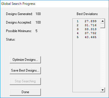
- Needle optimization, with tunneling to explore further designs, for specialized designs.
- Optimize layer thickness, refractive index, or both simultaneously.
- Display merit function deviation during optimization.
- Display refractive index profile during optimization.
- Flexible merit function setup.
- Simultaneously optimize front and back layers.
- Optimize group factors.
- Sensitivity optimization capability.
- Automatically remove zero-thickness layers during optimization.
- Input light source emission and detector sensitivity functions to optimize coatings for specific operational environments.
- Optimize the product of Reflectance × Transmittance (R · T).
- Optimization Targets: Reflectance, transmittance, absorptance, density, color, illuminance, phase shift, and psi across all wavelengths, polarizations, and angles. Supports discrete wavelengths or continuous ranges, 1st/2nd/3rd derivatives, manual entry, auto-generation, file importing, and inequality targets up to 10,000 points.
Results & Output
- [NEW] 3D plotting capability for wavelength × incident angle × characteristic value.
- [NEW] Overlay and simultaneously display color-coded coating calculation results on 2D plots.
- [NEW] Toggle display settings for color chart colors, color names, and boundary lines.
- Results displayed in numerical tables and graphical plots.
- Print complete data tables and charts.
- Save intermediate results to file before starting a new analysis.
- Display the current result together with up to 5 saved results on a single graph.
- Plot two parameters (e.g., reflectance and transmittance) on a single graph.
- Yield analysis (Monte Carlo) for manufacturing tolerances.
Optical Data
- [NEW] Character limit for custom component names (materials, substrates, etc.)
- Unlimited number of substrate, illuminant, detector, and radiation distribution data files.
- Input refractive index via tables or dispersion formulas.
- Import substrate internal transmittance data.
- Interpolate missing values for N or K.
- Compute refractive index (N, K) from spectral or ellipsometric data.
- Absorption and dispersion configurations for materials and substrates.
- Save coating reflectance or transmittance as illuminant data.
- Save data files with user annotations.
- Import text file data.
- Generate blackbody radiation spectra.
Coating Files
- [NEW] New unified file format (.tfd2) bundling design configurations, saved results, and 3D plot states.
- [NEW] Import and export support for legacy version files.
- Includes all coating-related parameters (layers, targets, annotations, materials, etc.).
- Easily copy and transfer coating files.
Accuracy & Performance
- [NEW] Dual calculation modes (Speed and Precision) with multi-core support.
- Precision mode computes with 28-digit decimal arithmetic; Speed mode uses double precision (about 16-digit).
User Interface
- [NEW] Intuitive Excel-style table UI with row/column transposition and Undo/Redo functionality.
- [NEW] Language toggle between English and Japanese.
- [NEW] Multi-Document Interface (MDI) for smooth concurrent design workflows across multiple windows.
- [NEW] Window snapping and alignment features.
- User-friendly standard Windows interface with spreadsheet-style dialogs and menus.
- Simple editing and recalculation.
History of TFCalc enhancements
- TFCalc 5.0 Changes
- TFCalc 3.6 Changes
- TFCalc 3.4 Changes
- TFCalc 3.3 Changes
- TFCalc 3.2 Changes
- TFCalc 3.1 Changes
- TFCalc 3.0 Changes
- TFCalc 2.9 Changes
- TFCalc 2.8 Changes
Why TFCalc?
- Easy to use
- A stable, reliable tool that runs on Windows
- Equipped with features required by coating designers
- Equipped with features not found in other design programs
- Unlimited definition of materials, substrates, and illuminants
- Setting variable indices for layers, and combining multiple materials on a single layer
- Provides a cost-effective solution
- Powerful optimization feature
- Needle optimization
- Global search
- Sensitivity optimization
- Cone-angle targets optimization
TFCalc is used in various research papers!
Case Study:
Empowering Optics Students with TFCalc for Coating Design
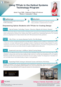
Alexis Vogt, PhD
Endowed Chair & Professor of Optics
Monroe Community College (NY, USA)
Research papers using TFCalc
| Design and experimental evaluation of TiO2/MgF2 dual-layer anti-reflection coatings for Nd- and Er-doped phosphate glass lasers |
|---|
| Le Van Dai 1, Do Thanh Tung 2, Pham Duc Tuan 1, Truong Hong Giang 1 1 Academy of Military Science and Technology, 17 Hoang Sam, Nghia Do, Hanoi, Vietnam 2 Institute of Technical Physics, 17 Hoang Sam, Nghia Do, Hanoi, Vietnam |
| DOI: https://doi.org/10.15625/0868-3166/22927 |
| (Abstract) This study focuses on the design and experimental evaluation of two-layer TiO2-MgF2 anti-reflection (AR) coatings on Nd- and Er-doped phosphate glass for laser applications at 1053 nm and 1535 nm. Using matrix theory and TFCalc software, the optimized design achieves reflectance close to 0% for Nd-doped glass and below 0.1% for Er-doped glass. The coatings were fabricated using the SYRUSpro 710 system, achieving experimental transmittance values of 99.7% in the 1050–1080 nm range and 99.8% in the 1530–1570 nm range, despite minor discrepancies between experimental and simulated results. The coating durability meets MIL-SPEC standards for mechanical testing. Additionally, laser-induced damage threshold (LIDT) measurements at 1064 nm yielded a 50% damage fluence of 13.2 J/cm² for the Nd-doped sample, demonstrating reliable laser resistance suitable for moderate-fluence solid-state laser applications. This research lays the foundation for optimizing coating processes and advancing the development of rare-earth-doped solid-state laser sources. |
| Anti-Reflective Coatings Produced via Atomic Layer Deposition for Hybrid Polymer 3D Micro-Optics |
|---|
| Darija Astrauskytė 1, Karolis Galvanauskas 2, Darius Gailevičius 2, Mantas Drazdys 1, Mangirdas Malinauskas 2,* and Lina Grineviciute 1,* 1 Center for Physical Sciences and Technology, Savanorių av. 231, LT-02300 Vilnius, Lithuania 2 Laser Research Center, Physics Faculty, Vilnius University, Saulėtekio av. 10, LT-10223 Vilnius, Lithuania * Authors to whom correspondence should be addressed. |
| Nanomaterials 2023, 13(16), 2281; https://doi.org/10.3390/nano13162281 |
| (Abstract) The increasing demand for optics quality requires the lowest optical power loss, which can occur from unwanted reflections. Laser direct writing (LDW) allows for the fabrication of complex structures, which is particularly advantageous in micro-optic applications. This research demonstrates the possibility of forming an anti-reflective coating on hybrid polymer micro-lenses fabricated by employing LDW without changing their geometry. Such coating deposited via atomic layer deposition (ALD) decreased the reflection from 3.3% to 0.1% at a wavelength of 633 nm for one surface of hybrid organic–inorganic SZ2080™ material. This research validates the compatibility of ALD with LDW 3D multiphoton lithography synergistically, expanding its applications on optical grade sub-100 μm scale micro-optics. |
| Polarization modeling and predictions for Daniel K. Inouye Solar Telescope part 5: impacts of enhanced mirror and dichroic coatings on system polarization calibration |
|---|
| David M. Harrington 1, Stacey R. Sueoka 1, Amanda J. White 1 1 National Solar Observatory (United States) |
| Journal of Astronomical Telescopes, Instruments, and Systems, Vol. 5, Issue 3, 038001 (Jun 2019) https://doi.org/10.1117/1.JATIS.5.3.038001 |
| (Abstract) The Daniel K. Inouye Solar Telescope (DKIST) is designed to deliver accurate spectropolarimetric calibrations across a wide wavelength range and large field of view for solar disk, limb, and coronal observations. DKIST instruments deliver spectral resolving powers of up to 300,000 in multiple cameras of multiple instruments sampling nanometer scale bandpasses. We require detailed knowledge of optical coatings on all optics to ensure that we can predict and calibrate the polarization behavior of the system. Optical coatings can be metals protected by many dielectric layers or several-micron-thick dichroics. Strong spectral gradients up to 60 deg retardance per nanometer wavelength and several percent diattenuation per nanometer wavelength are observed in such coatings. Often, optical coatings are not specified with spectral gradient targets for polarimetry in combination with both average- and spectral threshold-type specifications. DKIST has a suite of interchangeable dichroic beam splitters using up to 96 layers. We apply the Berreman formalism in open-source Python scripts to derive coating polarization behavior. We present high spectral resolution examples on dichroics where transmission can drop 10% with associated polarization changes over a 1-nm spectral bandpass in both mirrors and dichroics. We worked with a vendor to design dichroic coatings with relatively benign polarization properties that pass spectral gradient requirements and polarization requirements in addition to reflectivity. We now have the ability to fit multilayer coating designs which allow us to predict system-level polarization properties of mirrors, antireflection coatings, and dichroics at arbitrary incidence angles, high spectral resolving power, and on curved surfaces through optical modeling software packages. Performance predictions for polarization at large astronomical telescopes require significant metrology efforts on individual optical components combined with system-level modeling efforts. We show our custom-built laboratory spectropolarimeter and metrology efforts on protected metal mirrors, antireflection coatings, and dichroic mirror samples. |
System Requirements & Licensing Options
| Operating System | Windows 11 (64-bit native application) |
| Runtime Framework | .NET 10 Desktop Runtime (included in installer) |
| Graphics Environment | Graphics environment supporting OpenGL 3.3 or later (compatibility profile) required for 3D plotting. (All non-3D functions remain fully functional without OpenGL 3.3+). |
| Licensing Models | • Single User License: Installation on up to 2 PCs for 1 user (non-simultaneous). • Single Machine License: Installation on 1 PC for multiple users. |
Request a Free Trial or a Quote
- TFCalc 5 is a one-time purchase product, allowing for long-term use. The initial purchase includes one year of maintenance coverage.
- During the active maintenance period, you are entitled to free version upgrades. (You may continue to use TFCalc even if you choose not to renew your maintenance.)
- Volume discounts are available for multiple-license purchases. Users of versions 3.5 or 3.6 are eligible for special upgrade pricing.
- A special promotional campaign for new licenses is currently underway! (Valid until March 31, 2027)
TFCalc Product Installation Instructions
Installation instructions for V5: Please refer to the installation guide included with the product.
Installation instruction for v3.5.16 or later